Until recently, implants have been restored
with either PFM structures or removable partial dentures with denture teeth.
This article describes a new alternative to the implant restorative
protocol. Utilizing a new implant system and resin restorative material, it
is possible to create a quick, permanent chairside restoration without
generating laboratory fees. The following case describes the replacement of
a missing lower left first molar with a single implant restored chairside
with resin.
Case Report
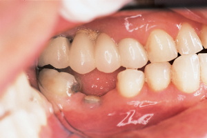
A 55-year-old male patient presented to our clinic
seeking replacement of his lower left first molar. The patient’s medical and
dental history was obtained in the usual manner. The history revealed a
healthy male with good oral hygiene, with no contraindications to implant
treatment. His major concern was to avoid conventional bridging, which
required the removal of sound tooth structure. He was not very happy with a
conventional bridge on the opposing arch, because of the tooth destruction
and the inability to clean the area easily. He stated, "Had I known about
implants earlier, I would have never consented to a conventional bridge
procedure." The Internet was his source of implant information, not his
previous dentist.
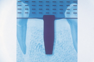
| Figure 1. Periapical
radiograph implant selector overlay guide. |
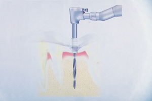
Figure 2. Surgical stent
guiding initial pilot hole. |
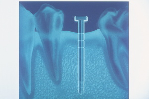
Figure 3. Periapical
radiograph with initial pilot hole gauge. |
| Figure 4. Soft tissue
circular trephine used to create surgical and implant placement
channel.. |
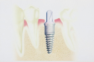
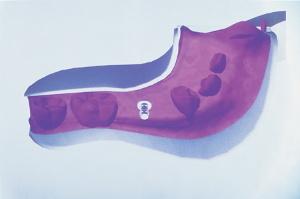
Figure 5. Implant in
place with healing cap in place. |
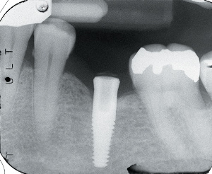
Figure 6. Radiograph of
the implant at progressive osseointegration evaluation appointment. |
During the initial visit, study models and a
periapical radiograph were obtained.A physical/visual examination was also
performed to determine buccal-lingual alveolar bone dimension. With this
information and a radiograph overlay implant selector (BASIC Dental Implant
Systems), a 4-mm by 15-mm implant was selected for placement (Figure 1).A
clear acrylic surgical stent was fabricated to guide the osteotomy drills
(Figure 2).
The patient was scheduled for a 30-minute surgical implant placement
appointment and was anesthetized with local anesthetic in the usual manner.
In a matter of minutes, we were ready to proceed. The pilot drill was sunk
to the predetermined depth, guided by the acrylic stent through the
unflapped gingival tissue. Because the amount of available bone was quite
abundant in this particular case, flapping was unnecessary. It has been my
experience that whenever possible, flapping the tissue should be avoided to
minimize discomfort and to speed healing time.1 Utilizing a conservative
surgical placement procedure greatly diminishes chair time and the patient's
reliance on analgesics postoperatively.
After the pilot hole was made, a depth gauge
indicator was placed into the pilot osteotomy, and a periapical radiograph
was obtained (Figure 3). This revealed the depth and mesial distal position
of the initial pilot hole prior to the final enlargement. This step is an
important conservative exploratory guide for the rest of the surgery.2 At
this point, a self-centering soft tissue trephine was placed into the pilot
hole, driven by a contra angle dental drill, and a circular, soft tissue
donut of tissue was cut down to the bone and removed, creating a precise
soft tissue channel to the alveolar bone (Figure 4). The
final enlargement was performed through this conservative channel, precisely
matching the diameter and depth of the implant.
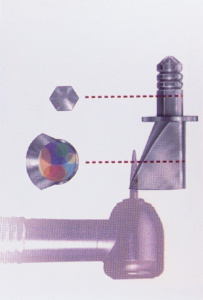
The BASIC implant used in this case is a self-tapping stage-one implant that
is screwed into place with a simple ratchet. This particular implant system
is unique because it utilizes a hex-recess hole that accommodates resin
cementable customized posts and cores.3 Because this particular protocol is
so quick, simple, and conservative, it is possible to obtain impression
records of the implant site and the opposing arch at the time of surgery.
Thirty minutes is more than adequate time required to perform this phase of
the implant treatment ( Figure 5).
The patient was dismissed with a prescription for a 10-day supply of
antibiotics and mild analgesics. Analgesics are used as required.4 The
patient was instructed to return at 2 months to verify progressive
osseointegration was taking place. There is no need to see the patient
earlier unless problems arise as described in the patient's home literature.
At 2 months the patient returned for a quick, 5-minute examination. A
periapical radiograph was obtained to verify an intimate bone-to-implant
surface contact. The implant was also examined physically and visually for
mobility, pain, and signs of infection. If the examination demonstrates a
lack of mobility, pain, and/or infection, and demonstrates intimate
bone-to-implant contact, progressive osseointegration; is established,
paving the way for prosthetic delivery (Figure 6).
| Figure 7. Implant with
IPTD firmly seated into place prior to impression. |
Figure 8. Impression with
IPTD re-indexed back into the impression. |
Figure 9. Impression with
IPTD and implant analog prior to adding stone. |
| Figure 10. Stone model
ready for prosthetic fabrication. |
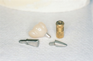
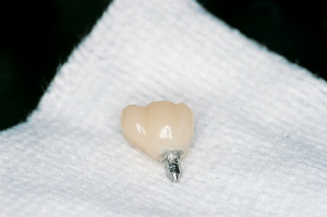
Figure 11. Prefabricated
post and core prior to modification. |
Figure 12. Post and core
before and after modification, and post and core with resin crown. |
The spatial position of the implant was obtained
by simply seating the implant position transfer device (IPTD) into the
implant and impressing with polyvinylsiloxane impression material (Figures 7
and 8). The IPTD does not usually dislodge when the impression is unseated
because of its tight fit in the implant. The IPTD was simply indexed back
into the set impression with the analog fully seated onto the stem (Figure
9). Cyanoacrylate was flowed into the IPTD analog and the impression to
eliminate possible movement during transportation to the lab and pouring of
the working model. The working model with the analog precisely embedded was
now ready for prosthetic fabrication (Figure 10). BASIC's unique
prefabricated post-core is designed to allow core customization, up to 20º
from the long axis, by simply cutting it back as desired with a dental drill
(Figure 11).
In this particular case, the models were returned, and the post and core
were customized in the clinic in a matter of minutes. A clear plastic crown
form with corresponding anatomy to the missing tooth was selected and
trimmed to fit the customized post and core. With the customized post and
core seated (not cemented) into the analog, the trimmed crown form was
loaded with resin of appropriate shade and seated over the modified core.
The resin was light cured onto the core and removed from the model. The
resin crown was then completely cured from all aspects, trimmed, and
polished.
The resin crown and the post and core were now ready for cementation with
resin cement to the implant (Figures 12 through 15). Palfique resin
restorative material (J. Morita) was chosen because of its aesthetics and
finishing properties. The resin's spherical filler allows much faster
finishing to chameleon-like shade match when compared with those utilizing
traditional nonspherical filler. Polishing was accomplished quickly with dry
pumice followed by wet pumice in a slow-rotating white prophy cup.
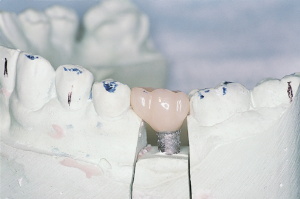
| Figure 13.
Note periodontal-friendly crown design. |
Figure 14.
Side view of crown on model. |
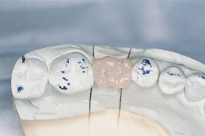
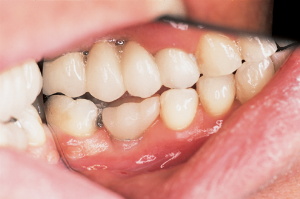
| Figure 15. Occlusal view
of the restoration with broad contact areas. |
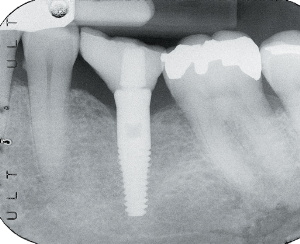
Figure 16. Periapical
radiograph of the restored implant. |
Figure 17. Restoration
cemented into place. |
The patient was now scheduled for a
30-minute prosthetic seating appointment. It was not necessary to
anesthetize the patient for this phase of the treatment. The healing cover
was removed, and the hex hole recess in the implant was gently dried. A
small amount of resin cement was dispensed, mixed, and applied to the hex
hole recess in the implant with a slender, pointed resin application brush
and wiped onto the inner walls of the hex hole in a circular motion. The
resin crown post;core assembly was then seated into the implant and allowed
to set. Cement flash was removed, and if required, the occlusion was
adjusted at this time. For this case, Rely-X resin cement (3M ESPE) was
chosen for cementation because of its ease of use and excellent performance
(Figures 16 and 17).
Conclusion
It is possible to fabricate excellent single-unit restorations, without the
participation of a dental laboratory, quickly and easily. This protocol is
highly profitable and versatile when compared with traditional laboratory
restorations. It is very easy to customize the shade and anatomy when the
dentist has complete control at chairside. For single-implant situations,
when the path of insertion is favorable, this protocol is a highly effective
and desirable alternative to other methods of implant restorations.
References
1. Campelo LD, Camara JR. Flapless implant surgery: a 10-year clinical
retrospective analysis. Int J Oral Maxillofac Implants. 2002;17:271-276.2.
BASIC dental implant surgical
and prosthetic manual. Available by contacting Dr. Walter Schuman, Director
of Education for BASIC Dental Implant Systems. (888) 888-1468.3. Squier RS,
Agart JR, Duncan JP, et al. Retentiveness of dental cements used with
metallic implant components. Int J Oral Maxillofac Implants.
2001;6:793-798.4. Wood DL,
Hoag PM, Donnenfeld et al. Alveolar crest reduction following full and
partial thickness flaps. J Periodontol. 1972;42:141-144.
Dr. Fernandes is in full-time general dental
practice in Winnipeg, Manitoba, Canada. He has a special interest in dental
implantology in general practice.
More articles
America's Dental Bookstore maintains this collection of articles on dentistry submitted by visitors to our site. These
could be clinical tips, research articles, opinion articles, dental jokes, or
whatever. Do you have something you'd like to submit? If so,
click here to submit an article.